1
/
of
1
Siemens - 6ES7132-6BD21-0BA0
Siemens - 6ES7132-6BD21-0BA0
Regular price
€44,32 EUR
Regular price
Sale price
€44,32 EUR
Couldn't load pickup availability
Low stock: 2 left
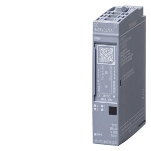
SIMATIC ET 200SP DQ 4x 24VDC/2A ST
| General information | ||
| Product type designation | DQ 4x24VDC/2A ST | |
| HW functional status | 01 | |
| Firmware version | V1.0 | |
| FW update possible | Yes | |
| usable BaseUnits | BU type A0 | |
| Color code for module-specific color identification plate | CC02 | |
| Product function | ||
| I&M data | Yes; I&M0 to I&M3 | |
| Isochronous mode | No | |
| Engineering with | ||
| STEP 7 TIA Portal configurable/integrated from version | STEP 7 V19 or higher with HSP0425 / integrated as of TIA Portal V20 | |
| STEP 7 configurable/integrated from version | as of STEP 7 V5.5 SP3 with HSP0230 V11.0 / integrated as of STEP 7 V5.7 SP3 | |
| PROFIBUS from GSD version/GSD revision | One GSD file each, Revision 3 and 5 and higher | |
| PROFINET from GSD version/GSD revision | GSDML V2.43 | |
| Operating mode | ||
| DQ | Yes | |
| DQ with energy-saving function | No | |
| PWM | No | |
| Oversampling | No | |
| MSO | No | |
| Supply voltage | ||
| Rated value (DC) | 24 V | |
| permissible range, lower limit (DC) | 19.2 V | |
| permissible range, upper limit (DC) | 28.8 V | |
| Reverse polarity protection | Yes | |
| Input current | ||
| Current consumption, max. | 20 mA; without load | |
| output voltage / header | ||
| Rated value (DC) | 24 V | |
| Power loss | ||
| Power loss, typ. | 1 W | |
| Address area | ||
| Address space per module | ||
| Address space per module, max. | 1 byte; + 1 byte for QI information | |
| Hardware configuration | ||
| Automatic encoding | Yes | |
| Mechanical coding element | Yes | |
| Type of mechanical coding element | Type A | |
| Selection of BaseUnit for connection variants | ||
| 1-wire connection | BU type A0 | |
| 2-wire connection | BU type A0 | |
| 3-wire connection | BU type A0 with AUX terminals or potential distributor module | |
| Digital outputs | ||
| Type of digital output | Source output (PNP, current-sourcing) | |
| Number of digital outputs | 4 | |
| Current-sinking | No | |
| Current-sourcing | Yes | |
| Digital outputs, parameterizable | Yes | |
| output type acc. to IEC 61131, type 2 | Yes | |
| Short-circuit protection | Yes; Electronic | |
| Response threshold, typ. | 2.8 to 5.2 A | |
| Open-circuit detection | Yes | |
| Limitation of inductive shutdown voltage to | Typ. L+ (-50 V) | |
| Controlling a digital input | Yes; supports input type 3 according to IEC 61131-2 | |
| Switching capacity of the outputs | ||
| with resistive load, max. | 2 A | |
| with inductive load, max. | 2 A | |
| on lamp load, max. | 10 W | |
| Load resistance range | ||
| lower limit | 12 ¦ | |
| upper limit | 3 400 ¦ | |
| Output current | ||
| for signal "1" rated value | 2 A | |
| for signal "1" permissible range, max. | 2 A | |
| for signal "0" residual current, max. | 0.1 mA | |
| Output delay with resistive load | ||
| "0" to "1", typ. | 50 µs | |
| "1" to "0", typ. | 100 µs | |
| Parallel switching of two outputs | ||
| for uprating | No | |
| for redundant control of a load | Yes | |
| Switching frequency | ||
| with resistive load, max. | 100 Hz | |
| with inductive load, max. | 0.1 Hz; higher frequencies are possible, see Equipment Manual "Maximum permitted switching frequency of inductive loads" | |
| on lamp load, max. | 10 Hz | |
| Total current of the outputs | ||
| Current per channel, max. | 2 A | |
| Current per module, max. | 8 A; see Equipment Manual "Derating curve" | |
| Total current of the outputs (per module) | ||
| horizontal installation | ||
| up to 30 °C, max. | 8 A | |
| up to 40 °C, max. | 8 A | |
| up to 50 °C, max. | 6 A | |
| up to 60 °C, max. | 4 A | |
| vertical installation | ||
| up to 30 °C, max. | 8 A | |
| up to 40 °C, max. | 6 A | |
| up to 50 °C, max. | 4 A | |
| Cable length | ||
| shielded, max. | 1 000 m | |
| unshielded, max. | 600 m | |
| Interrupts/diagnostics/status information | ||
| Diagnostics function | Yes | |
| Substitute values connectable | Yes | |
| Alarms | ||
| Diagnostic alarm | Yes | |
| Diagnoses | ||
| Monitoring the supply voltage | Yes | |
| parameterizable | Yes | |
| Wire-break | Yes; Module-wise | |
| Short-circuit to M | Yes; Module-wise | |
| Short-circuit to L+ | Yes; Module-wise | |
| Group error | Yes | |
| Diagnostics indication LED | ||
| Monitoring of the supply voltage (PWR-LED) | Yes; green PWR LED | |
| Channel status display | Yes; green LED | |
| for channel diagnostics | No | |
| for module diagnostics | Yes; green/red DIAG LED | |
| Potential separation | ||
| Potential separation channels | ||
| between the channels | No | |
| between the channels and backplane bus | Yes | |
| Between the channels and load voltage L+ | No | |
| Isolation | ||
| Isolation tested with | 707 V DC (type test) | |
| Standards, approvals, certificates | ||
| Suitable for safety functions | No | |
| Ambient conditions | ||
| Ambient temperature during operation | ||
| horizontal installation, min. | -30 °C | |
| horizontal installation, max. | 60 °C | |
Share