1
/
of
1
Siemens - 6ES7134-6GB00-0BA1
Siemens - 6ES7134-6GB00-0BA1
Regular price
€91,04 EUR
Regular price
Sale price
€91,04 EUR
Couldn't load pickup availability
33 in stock
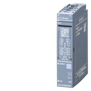
SIMATIC ET 200SP AI 2xI 2-/4-wire ST
| General information | ||
| Product type designation | AI 2xI 2-/4-wire ST | |
| HW functional status | from FS04 | |
| Firmware version | ||
| FW update possible | Yes | |
| usable BaseUnits | BU type A0, A1 | |
| Color code for module-specific color identification plate | CC05 | |
| Product function | ||
| I&M data | Yes; I&M0 to I&M3 | |
| Isochronous mode | No | |
| Measuring range scalable | No | |
| Engineering with | ||
| STEP 7 TIA Portal configurable/integrated from version | V13 SP1 | |
| STEP 7 configurable/integrated from version | V5.5 SP3 | |
| PROFIBUS from GSD version/GSD revision | One GSD file each, Revision 3 and 5 and higher | |
| PROFINET from GSD version/GSD revision | V2.3 / - | |
| Operating mode | ||
| Oversampling | No | |
| MSI | No | |
| CiR - Configuration in RUN | ||
| Reparameterization possible in RUN | Yes | |
| Calibration possible in RUN | No | |
| Supply voltage | ||
| Rated value (DC) | 24 V | |
| permissible range, lower limit (DC) | 19.2 V | |
| permissible range, upper limit (DC) | 28.8 V | |
| Reverse polarity protection | Yes | |
| Input current | ||
| Current consumption, max. | 45 mA; without sensor supply | |
| Encoder supply | ||
| 24 V encoder supply | ||
| 24 V | Yes | |
| Short-circuit protection | Yes | |
| Output current, max. | 50 mA; Total current for both channels (two-wire) | |
| Additional 24 V encoder supply | ||
| 24 V | Yes | |
| Short-circuit protection | Yes; Module-wise | |
| Output current, max. | 200 mA; Total current for both channels (four-wire) | |
| Power loss | ||
| Power loss, typ. | 1.1 W | |
| Address area | ||
| Address space per module | ||
| Address space per module, max. | 4 byte; + 1 byte for QI information | |
| Hardware configuration | ||
| Automatic encoding | Yes | |
| Mechanical coding element | Yes | |
| Type of mechanical coding element | Type A | |
| Selection of BaseUnit for connection variants | ||
| 1-wire connection | BU type A0, A1 | |
| 2-wire connection | BU type A0, A1 | |
| 4-wire connection | BU type A0, A1 | |
| Analog inputs | ||
| Number of analog inputs | 2 | |
| For current measurement | 2 | |
| permissible input current for current input (destruction limit), max. | 50 mA | |
| Cycle time (all channels), min. | 500 µs | |
| Input ranges (rated values), currents | ||
| 0 to 20 mA | Yes; 15 bit | |
| Input resistance (0 to 20 mA) | 130 ¦; 90 ohms with two wires | |
| -20 mA to +20 mA | Yes; 16 bit incl. sign | |
| Input resistance (-20 mA to +20 mA) | 130 ¦ | |
| 4 mA to 20 mA | Yes; 15 bit | |
| Input resistance (4 mA to 20 mA) | 130 ¦; 90 ohms with two wires | |
| Cable length | ||
| shielded, max. | 1 000 m | |
| Analog value generation for the inputs | ||
| Measurement principle | Sigma Delta | |
| Integration and conversion time/resolution per channel | ||
| Resolution with overrange (bit including sign), max. | 16 bit | |
| Integration time, parameterizable | Yes | |
| Interference voltage suppression for interference frequency f1 in Hz | 16.6 / 50 / 60 Hz / off | |
| Conversion time (per channel) | 50 ms @ 60 Hz, 60 ms @ 50 Hz, 180 ms @ 16.6 Hz, 500 µs without filter | |
| Smoothing of measured values | ||
| Number of smoothing levels | 4 | |
| parameterizable | Yes | |
| Step: None | Yes; 1x conversion time | |
| Step: low | Yes; 4x conversion time | |
| Step: Medium | Yes; 8x conversion time | |
| Step: High | Yes; 16x conversion time | |
| Encoder | ||
| Connection of signal encoders | ||
| for current measurement as 2-wire transducer | Yes | |
| Burden of 2-wire transmitter, max. | 650 ¦ | |
| for current measurement as 4-wire transducer | Yes | |
| Errors/accuracies | ||
| Linearity error (relative to input range), (+/-) | 0.01 % | |
| Temperature error (relative to input range), (+/-) | 0.005 %/K | |
| Crosstalk between the inputs, min. | -50 dB | |
| Repeat accuracy in steady state at 25 °C (relative to input range), (+/-) | 0.05 % | |
| Operational error limit in overall temperature range | ||
| Current, relative to input range, (+/-) | 0.5 % | |
| Basic error limit (operational limit at 25 °C) | ||
| Current, relative to input range, (+/-) | 0.3 % | |
| Interference voltage suppression for f = n x (f1 +/- 1 %), f1 = interference frequency | ||
| Series mode interference (peak value of interference < rated value of input range), min. | 70 dB | |
| Common mode voltage, max. | 10 V | |
| Common mode interference, min. | 90 dB | |
| Interrupts/diagnostics/status information | ||
| Diagnostics function | Yes | |
| Alarms | ||
| Diagnostic alarm | Yes | |
| Limit value alarm | No | |
| Diagnoses | ||
| Monitoring the supply voltage | Yes | |
| Wire-break | Yes; at 4 to 20 mA | |
| Short-circuit | Yes; Short-circuit of the encoder supply | |
| Group error | Yes | |
| Overflow/underflow | Yes | |
| Diagnostics indication LED | ||
| Monitoring of the supply voltage (PWR-LED) | Yes; green PWR LED | |
| Channel status display | Yes; green LED | |
| for channel diagnostics | No | |
| for module diagnostics | Yes; green/red DIAG LED | |
| Potential separation | ||
| Potential separation channels | ||
| between the channels | No | |
| between the channels and backplane bus | Yes | |
| between the channels and the power supply of the electronics | Yes | |
| Permissible potential difference | ||
| between the inputs (UCM) | 10 Vpp | |
| Isolation | ||
Share