1
/
of
1
Siemens - 6ES7136-6AA00-0CA1
Siemens - 6ES7136-6AA00-0CA1
Regular price
€344,37 EUR
Regular price
Sale price
€344,37 EUR
Couldn't load pickup availability
Low stock: 6 left
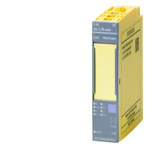
SIMATIC DP F-AI 4xI 0(4)...20mA 2-/4-wire HF
| General information | ||
| Product type designation | F-AI 4xI 0(4)..20mA 2-/4-wire HF | |
| Firmware version | ||
| FW update possible | Yes | |
| usable BaseUnits | BU type A0, A1 | |
| Color code for module-specific color identification plate | CC00 | |
| Product function | ||
| I&M data | Yes; I&M0 to I&M3 | |
| Engineering with | ||
| STEP 7 TIA Portal configurable/integrated from version | V15 with HSP 203 | |
| CiR - Configuration in RUN | ||
| Reparameterization possible in RUN | No | |
| Calibration possible in RUN | No | |
| Supply voltage | ||
| Rated value (DC) | 24 V | |
| permissible range, lower limit (DC) | 19.2 V | |
| permissible range, upper limit (DC) | 28.8 V | |
| Reverse polarity protection | Yes | |
| power supply according to NEC Class 2 required | No | |
| Input current | ||
| Current consumption (rated value) | 0.38 A | |
| Current consumption, max. | 0.4 A | |
| Encoder supply | ||
| 24 V encoder supply | ||
| 24 V | Yes; min. L+ (-1.5 V) | |
| Short-circuit protection | Yes | |
| Output current, max. | 300 mA; total current of all encoders/channels | |
| Power | ||
| Power consumption from the backplane bus | 70 mW | |
| Power loss | ||
| Power loss, typ. | 2 W | |
| Address area | ||
| Address space per module | ||
| Inputs | 14 byte; S7-300/400F CPU, 13 byte | |
| Outputs | 5 byte; S7-300/400F CPU, 4 byte | |
| Hardware configuration | ||
| Automatic encoding | Yes | |
| Electronic coding element type F | Yes | |
| Analog inputs | ||
| Number of analog inputs | 4 | |
| For current measurement | 4 | |
| permissible input current for current input (destruction limit), max. | 35 mA | |
| Input ranges (rated values), currents | ||
| 0 to 20 mA | Yes | |
| Input resistance (0 to 20 mA) | 125 ¦ | |
| 4 mA to 20 mA | Yes | |
| Input resistance (4 mA to 20 mA) | 125 ¦ | |
| Cable length | ||
| shielded, max. | 1 000 m | |
| Analog value generation for the inputs | ||
| Measurement principle | Sigma Delta | |
| Integration and conversion time/resolution per channel | ||
| Resolution with overrange (bit including sign), max. | 16 bit | |
| Integration time, parameterizable | Yes | |
| Integration time (ms) | 20 / 16,667 | |
| Interference voltage suppression for interference frequency f1 in Hz | 50 / 60 Hz | |
| Smoothing of measured values | ||
| Number of smoothing levels | 7 | |
| parameterizable | Yes | |
| Step: None | Yes; 1x conversion cycle time | |
| Step: low | Yes; 2x / 4x conversion cycle time | |
| Step: Medium | Yes; 8x / 16x conversion cycle time | |
| Step: High | Yes; 32x / 64x conversion cycle time | |
| Encoder | ||
| Connection of signal encoders | ||
| for current measurement as 2-wire transducer | Yes | |
| Burden of 2-wire transmitter, max. | 650 ¦ | |
| for current measurement as 4-wire transducer | Yes | |
| Errors/accuracies | ||
| Linearity error (relative to input range), (+/-) | 0.1 % | |
| Temperature error (relative to input range), (+/-) | 0.023 %/K | |
| Repeat accuracy in steady state at 25 °C (relative to input range), (+/-) | 0.1 % | |
| Operational error limit in overall temperature range | ||
| Current, relative to input range, (+/-) | 2 % | |
| Basic error limit (operational limit at 25 °C) | ||
| Current, relative to input range, (+/-) | 0.1 % | |
| Interference voltage suppression for f = n x (f1 +/- 1 %), f1 = interference frequency | ||
| Series mode interference (peak value of interference < rated value of input range), min. | 40 dB | |
| Common mode interference, min. | 70 dB | |
| Interrupts/diagnostics/status information | ||
| Diagnostics function | Yes | |
| Alarms | ||
| Diagnostic alarm | Yes | |
| Limit value alarm | No | |
| Diagnoses | ||
| Monitoring the supply voltage | Yes | |
| Wire-break | Yes | |
| Short-circuit | Yes | |
| Diagnostics indication LED | ||
| RUN LED | Yes; green LED | |
| ERROR LED | Yes; red LED | |
| Monitoring of the supply voltage (PWR-LED) | Yes; green PWR LED | |
| Channel status display | Yes; green LED | |
| for channel diagnostics | Yes; red LED | |
| for module diagnostics | Yes; green/red DIAG LED | |
| Potential separation | ||
| Potential separation channels | ||
| between the channels | No | |
| between the channels and backplane bus | Yes | |
| between the channels and the power supply of the electronics | Yes | |
| Permissible potential difference | ||
| between the inputs (UCM) | 10 Vpp | |
| Isolation | ||
| Isolation tested with | 707 V DC (type test) | |
| Standards, approvals, certificates | ||
| Ecological footprint | ||
| environmental product declaration | Yes | |
| Global warming potential | ||
| global warming potential, (total) [CO2 eq] | 88.3 kg | |
| global warming potential, (during production) [CO2 eq] | 13.1 kg | |
| global warming potential, (during operation) [CO2 eq] | 76.6 kg | |
| global warming potential, (after end of life cycle) [CO2 eq] | -1.37 kg | |
| Highest safety class achievable in safety mode | ||
| Performance level according to ISO 13849-1 | PLe | |
| Category according to ISO 13849-1 | Cat. 4 | |
| SIL acc. to IEC 61508 | SIL 3 | |
| Probability of failure (for service life of 20 years and repair time of 100 hours) | ||
| Low demand mode: PFDavg in accordance with SIL3 | < 5.00E-05 | |
| High demand/continuous mode: PFH in accordance with SIL3 | < 1.00E-09 1/h | |
| Ambient conditions | ||
| Ambient temperature during operation | ||
| horizontal installation, min. | 0 °C | |
Share