1
/
of
1
Siemens - 6ES7146-5FF00-0BA0
Siemens - 6ES7146-5FF00-0BA0
Regular price
€323,97 EUR
Regular price
Sale price
€323,97 EUR
Couldn't load pickup availability
Low stock: 1 left
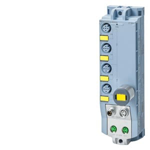
SIMATIC DP 4 F-DI/2 F-DQ DC 24V/2A 4x M12 PROFIsafe
| General information | ||
| Product type designation | F-DI 4+F-DQ 2x24VDC/2A, 4xM12 | |
| Product function | ||
| I&M data | Yes; I&M0 to I&M3 | |
| Engineering with | ||
| STEP 7 TIA Portal configurable/integrated from version | STEP 7 V17 or higher | |
| Operating mode | ||
| DI | Yes | |
| DQ | Yes | |
| Supply voltage | ||
| Rated value (DC) | 24 V | |
| power supply according to NEC Class 2 required | No | |
| Load voltage 1L+ | ||
| Rated value (DC) | 24 V | |
| permissible range, lower limit (DC) | 20.4 V | |
| permissible range, upper limit (DC) | 28.8 V | |
| Reverse polarity protection | Yes; against destruction | |
| Load voltage 2L+ | ||
| Rated value (DC) | 24 V | |
| permissible range, lower limit (DC) | 20.4 V | |
| permissible range, upper limit (DC) | 28.8 V | |
| Reverse polarity protection | Yes; against destruction; outputs applied with reversed polarity for loads connected between M-switch and 2L+ will conduct | |
| Input current | ||
| Current consumption (rated value) | 55 mA (1L+) / 40 mA (2L+); without load | |
| from load voltage 1L+ (unswitched voltage) | 4 A; Maximum value | |
| from load voltage 2L+, max. | 4 A; Maximum value | |
| Encoder supply | ||
| Number of outputs | 2 | |
| 24 V encoder supply | ||
| Short-circuit protection | Yes; per load voltage, electronic (response threshold 0.7 A to 1.7 A) | |
| Output current, max. | 1 A; total current of all encoders, max. 0.5 A per load voltage; maximum of 2.0 V drop | |
| Power loss | ||
| Power loss, typ. | 4.7 W | |
| Address area | ||
| Address space per module | ||
| Inputs | 8 byte | |
| Outputs | 6 byte | |
| Digital inputs | ||
| Number of digital inputs | 4 | |
| Input characteristic according to IEC 61131 | Type 1 | |
| Number of simultaneously controllable inputs | ||
| all mounting positions | ||
| up to 55 °C, max. | 4 | |
| Input voltage | ||
| Rated value (DC) | 24 V | |
| for signal "0" | -30 to +5 V | |
| for signal "1" | +15 to +30 V | |
| Input current | ||
| for signal "1", typ. | 4.85 mA | |
| Input delay (for rated value of input voltage) | ||
| for standard inputs | ||
| parameterizable | Yes | |
| at "0" to "1", min. | 0.8 ms | |
| at "0" to "1", max. | 12.8 ms | |
| at "1" to "0", min. | 0.8 ms | |
| at "1" to "0", max. | 12.8 ms | |
| Cable length | ||
| unshielded, max. | 30 m | |
| Digital outputs | ||
| Number of digital outputs | 2 | |
| in groups of | 2 | |
| Short-circuit protection | Yes; per channel, electronic | |
| Response threshold, typ. | 10 A; measured at M-switch, threshold for P-switch is higher | |
| Open-circuit detection | Yes; per channel, only detects when output is off | |
| Overload protection | Yes | |
| Response threshold, typ. | 3.4 A; measured at P-switch | |
| Limitation of inductive shutdown voltage to | P-switch: -26 V DC referenced to 2M, M-switch: +48 V DC referenced to 2M | |
| Switching capacity of the outputs | ||
| on lamp load, max. | 10 W | |
| Load resistance range | ||
| lower limit | 12 ¦ | |
| upper limit | 2 k¦ | |
| Output voltage | ||
| for signal "1", min. | L+ (-2.0 V), P-switch is L+ (-1.5 V), M-switch is 0.5 V | |
| Output current | ||
| for signal "1" rated value | 2 A | |
| for signal "0" residual current, max. | 0.5 mA | |
| Switching frequency | ||
| with resistive load, max. | 30 Hz | |
| with inductive load, max. | 0.1 Hz | |
| on lamp load, max. | 10 Hz | |
| Total current of the outputs | ||
| Current per group, max. | 4 A | |
| Cable length | ||
| unshielded, max. | 30 m | |
| Encoder | ||
| Connectable encoders | ||
| 2-wire sensor | No | |
| permissible quiescent current (2-wire sensor), max. | 0.5 mA | |
| Interrupts/diagnostics/status information | ||
| Substitute values connectable | No | |
| Alarms | ||
| Diagnostic alarm | Yes; Parameterizable | |
| Diagnoses | ||
| Monitoring the supply voltage | Yes | |
| Wire-break | Yes; outputs when off | |
| Short-circuit | Yes; inputs, outputs, encoder supply | |
| Diagnostics indication LED | ||
| Channel status display | Yes; green LED | |
| for channel diagnostics | Yes; red LED | |
| for module diagnostics | Yes; green/red LED | |
| For load voltage monitoring | Yes; green LED | |
| Potential separation | ||
| between the load voltages | Yes | |
| Potential separation channels | ||
| between the channels, in groups of | 4 DI channels are isolated from 2 DQ channels | |
| between the channels and backplane bus | Yes | |
| between the channels and the power supply of the electronics | DI channels are non-isolated from supply voltage 1L+ and DQ channels are isolated from the supply voltage 1L+ | |
| Isolation | ||
| Isolation tested with | 707 V DC (type test) | |
| Degree and class of protection | ||
| IP degree of protection | IP65/67 | |
| Standards, approvals, certificates | ||
| Highest safety class achievable in safety mode | ||
| Performance level according to ISO 13849-1 | PLd (DI single-channel), PLe (DI two-channel, DQ) | |
| Category according to ISO 13849-1 | Cat. 3 (DI single-channel), Cat. 4 (DI two-channel, DQ) | |
| SIL acc. to IEC 61508 | SIL 2 (DI single-channel), SIL 3 (DI two-channel, DQ) | |
| Probability of failure (for service life of 20 years and repair time of 100 hours) | ||
| Low demand mode: PFDavg in accordance with SIL2 | < 1.00E-03 DI single-channel; < 1.00E-03 DQ with dark test disabled | |
| Low demand mode: PFDavg in accordance with SIL3 | < 1.00E-05 DI two-channel; < 2.00E-05 DQ with dark test enabled | |
| High demand/continuous mode: PFH in accordance with SIL2 | < 1.00E-08 1/h DI single-channel; < 1.00E-07 1/h DQ with dark test disabled | |
Share