1
/
of
1
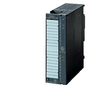
Siemens - 6ES7331-7TB00-0AB0
Siemens - 6ES7331-7TB00-0AB0
Regular price
€353,93 EUR
Regular price
Sale price
€353,93 EUR
Couldn't load pickup availability
Low stock: 1 left
SIMATIC DP SM 331 2 AI 0/4-20mA HART
| Supply voltage | ||
| Load voltage L+ | ||
| Rated value (DC) | 24 V | |
| Reverse polarity protection | Yes | |
| Input current | ||
| from load voltage L+ (without load), max. | 180 mA | |
| from backplane bus 5 V DC, max. | 100 mA | |
| output voltage / header | ||
| supply voltage of the transmitters / header | ||
| present | Yes | |
| Rated value (DC) | 15 V; at 22 mA | |
| short-circuit proof | Yes; approx. 30 mA | |
| No-load voltage (DC) | 29.6 V | |
| Power loss | ||
| Power loss, typ. | 4.5 W | |
| Analog inputs | ||
| Number of analog inputs | 2 | |
| permissible input current for current input (destruction limit), max. | 40 mA | |
| Input ranges (rated values), currents | ||
| 0 to 20 mA | Yes | |
| Input resistance (0 to 20 mA) | 50 ¦ | |
| 4 mA to 20 mA | Yes | |
| Input resistance (4 mA to 20 mA) | 50 ¦ | |
| Cable length | ||
| shielded, max. | 400 m | |
| Analog value generation for the inputs | ||
| Measurement principle | Sigma Delta | |
| Integration and conversion time/resolution per channel | ||
| Resolution with overrange (bit including sign), max. | 16 bit; 10 bit to 15 bit + sign | |
| Integration time, parameterizable | Yes | |
| Integration time (ms) | 2,5 / 16,67 / 20 / 100 ms | |
| Basic conversion time, including integration time (ms) | 2.5 / 16.67 / 20 / 100 (1 channel enabled); 7.5 / 50 / 60 / 300 (2 channels enabled) | |
| Interference voltage suppression for interference frequency f1 in Hz | 10 / 50 / 60 / 400 Hz | |
| Encoder | ||
| Connection of signal encoders | ||
| for current measurement as 2-wire transducer | Yes | |
| for current measurement as 4-wire transducer | Yes | |
| Errors/accuracies | ||
| Operational error limit in overall temperature range | ||
| Current, relative to input range, (+/-) | 0.45 %; From 0/4 to 20 mA | |
| Basic error limit (operational limit at 25 °C) | ||
| Current, relative to input range, (+/-) | 0.1 %; From 0/4 to 20 mA | |
| Interrupts/diagnostics/status information | ||
| Diagnostics function | Yes; can be set in parameters, red LED, alarm message | |
| Alarms | ||
| Diagnostic alarm | Yes; Parameterizable | |
| Limit value alarm | Yes; Parameterizable, channels 0 and 1 | |
| Diagnoses | ||
| Overrange | Yes; red LED, signal | |
| Wire-break in signal transmitter cable | Yes; red LED, signal | |
| Short-circuit of the signal encoder cable | Yes; red LED, signal | |
| HART communication active | Yes; green LED (H) | |
| Diagnostics indication LED | ||
| Group error SF (red) | Yes | |
| Channel fault indicator F (red) | Yes | |
| Ex(i) characteristics | ||
| Module for Ex(i) protection | Yes | |
| maximum values for connecting terminals for gas group IIC | ||
| Uo (no-load voltage), max. | 26 V | |
| Io (short-circuit current), max. | 96.1 mA | |
| Po (power output), max. | 511 mW | |
| Co (permissible external capacity), max. | 62 nF | |
| Lo (permissible external inductivity), max. | 3 mH | |
| Um (voltage at non-intrinsically safe connecting terminals), max. | 250 V; DC | |
| Potential separation | ||
| Potential separation analog inputs | ||
| between the channels | Yes | |
| between the channels and backplane bus | Yes | |
| Permissible potential difference | ||
| between the inputs (UCM) | 60 V DC/30 V AC | |
| Standards, approvals, certificates | ||
| FM approval | in preparation | |
| Use in hazardous areas | ||
| ATEX marking | II3 (2) G Eex nA [ib] IIC T4 | |
| ATEX certificate | KEMA 97 ATEX 3039X | |
| FM marking | Class I, Division 2, Group A, B, C, D T4; Class I, Zone 2, Group IIC T4 | |
| Ambient conditions | ||
| Ambient temperature during operation | ||
| min. | 0 °C | |
| max. | 60 °C | |
| Dimensions | ||
| Width | 40 mm | |
| Height | 125 mm | |
| Depth | 120 mm | |
| Weights | ||
| Weight, approx. | 260 g | |
| Approvals / Certificates | ||
Share